Tuesday 30 June 2015

Incidence Measuring Tool

Being a fairly recent adopter of Smart Phones, I was delighted to discover that there are several rather useful applications that can be adapted for Aeromodelling.

One of these is a 'Bubble app', freely available for iPhones and Androids.

I have started to use this extensively on my Kwik Fli build but what I really needed was an Incidence Measuring Tool. I have put off buying a commercial tool due to the relative high cost, mainly I suspect, due to the cost of the meter. The Bubble App has a resolution of 0.1 degrees and appears to be quite repeatable - i.e. the results are consistent which is very reassuring.

This, therefore is my Incidence Tool. I make no excuse - the basis of the design is a copy of those commercially available, however, I made mine in an evening from (mainly) offcuts of builders ply that I had lying round. It only cost me my time.

Design Overview

The design is quite straightforward:


It comprises of one fixed leg, the other is free to slide down the beam. My beam is 450mm long - this means that I can separate the legs by 390mm - about 15" - which is large enough for the foreseeable future. The legs and beam are 35mm wide, the leg length is 190mm long (top to bottom)

Construction Notes

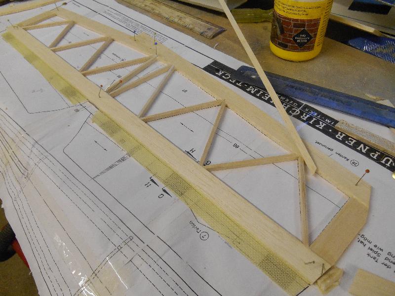
The really critical part of the tool is the length of the leg to the centre of the 'VEE' which locate on the LE and TE of the wing. The legs need to be at 90 degrees to the beam and the VEE must be at the came distance or the platform will not be level. It is quite easy to check when assembled, but if it is wrong, it much more difficult to correct.

The legs are reinforced on each side by 2 laminations of 3.6mm ply - 100mm long. On the diagram, the left leg is glued firmly into place, the right leg slides up and down the beam. It needs to slide quite freely but without being too loose. Before the right leg was glued up (PVA), I lubricated the beam with Beeswax. This prevent glue sticking to it and allows a nice smooth action.

The platform is a simple (in my case iPhone4 sized) ply platform inlaid into the top of the beam. Again, this needs to be parallel with the beam. I pinned it into place with a couple of panel pins and ensured that it was square by using balsa triangle section on each side of the joint between the beam and the platform.


Make sure the VEEs are the same length and size. Note, it is more important that these are square with each other rather than the legs being the same length.


Weighted down while the glue dried


This shot shows the doublers in place. These were sanded down with a nice curved edge when the glue dried

This shows the general arrangement quite well (even though the photo is on its side). The elastic band pulls the legs together when its in use


The Smartphone platform inlaid into the top of the beam


Using the Incidence Meter with a Smartphone

Download and install the App from your favourite App Store. I have the free version of 'Surface Level' which is one of a suite of potentially useful measuring tools. The little banner at the bottom of the App had adverts running all the time which the commercial version doesn't have.

Calibrate the Tool.

Place the model in a stand so that it is held quite firmly, it needs to be approximately level, but it's not critical.

Place the Jig on the wing, place the smartphone on the platform and zero the Application. Reverse the tool on the wing and without altering the Smartphone calibration, the incidence axis should still be zero degrees. If its not then you have an error in your construction and will need to make an alteration to the centre line of one of the two Vees. Over 300mm, an error of 0.1 degrees is about 0.5mm out..


Using the Tool

On most (not all) models the tailplane is set at 0 (zero) degrees to the Fuselage Datum. This is the case with the Kwik Fli used for the demonstration. If the tailplane is not set with the datum, then you will need to zero the application on the Datum first, then measure the wing and tail separately to find the Decalage.  (The difference between the incidences of the wing and tail or upper and lower wings in a biplane)

Place the smartphone on the tailplane and press the calibrate button. This will zero the bubble and X and Y should be set to 0.0 degrees.


Place the tool so that it is clamped between the LE and TE, somewhere near the wing root although it could be anywhere down the wing


Transfer the phone from the tailplane to the platform and measure the incidence. On this app, its the 'Y' axis that shows we have 0.4 degrees positive incidence. Check that its positive by lifting the phone very slightly at the LE side and the value should increase without going through zero first.

Measure Washout or Washin

Simply by measuring the incidence at the root then measuring again at the wingtip, the difference  determines any warps (intentional or otherwise). With the wing the right way up, less incidence at the tip means that the wing is washed out. You do need to ensure that the weight of the Incidence tool is not causing the wing to bend or twist.

Tuesday 16 June 2015

Glass Slipper (2)

This is another moment of madness - a parallel build while the Kwik Fli is in progress

Again, this is documented more thoroughly on Model Flying Forum

This is my own design very curvy Slope Soarer - designed to look like a moulded model but using very traditional construction methods - and lots of planking..

The jig was described in an earlier post, so now I have started the construction. The parts were supplied by Lasercraft Services in Cumbria from DXF files that I produced using DevFus and DraftSight.


Broadly, there is a horizontal crutch with each side made from 3 laminations of 1/8 sq spruce. The crutch sits in the jig which holds it straight while the formers are added (10 off)


This photo shows a better arrangement. The backbone also comprises of 3 laminations of 1/8 sq spruce

And when the glue is dry, you can start planking. At the top (and bottom) where the fuselage curves quite a lot in cross section the planks will be quite narrow - I have cut 1/8 square balsa then bevelled one edge - always keep the second edge square and bevel the next strip to fit.


It's a very slow process as you need the glue to dry on the previous piece before you start the next. I use PVA - but as its summer and quite warm its only taking about 30 minutes before the next piece can be fitted - still quite slow - but very therapeutic

 
This is a shot from the end after 4 planks have been fitted. it looks horrendous but the step is actually less than 1/32" and that is the sharpest of the curves I have to get the planks to fit round. It will easily sand smooth

Kwik Fli IV (2)

This is going together very quickly - the mix of insomnia, spare workshop time and nothing broken has given me a  rare window of Summer build activity.

The full build blog is here on the Model Flying Forum

 A few photos and a bit of description

 
 The fuselage went together very quickly. Basically, its a box with corner reinforcement. I have made a couple of minor changes to simplify it further - hopefully keeping the weight down and the fuselage straight
 

It looks like this after the formers and sides have been added.

 
The top deck is light 3/8 sheet balsa that sits on the 1/2" square longerons. This is carved and sanded down to a nice curved cross section profile


The tailplane is hollow - hinges are made from Kevlar sailcloth which I find to be very tough.


When complete, its sheeted top and bottom in 1/16" balsa. Light and strong


For the first time, I used a bubble app on a smartphone to align the tailplane. The upper deck is parallel to the fuselage datum so it was quite simple to set the fuselage level then move the phone onto the tailplane and make the minor tweaks to get the tailplane level and horizontal. I still use the three point method to check that the tail wasn't twisted. Basically, this involves using a length of string, measuring from the tip of the tail to the centre of the deck at the front and adjusting so that the distance to both tips is the same. Easier to write than do - quite a fiddly exercise


The fin was aligned using a laser alignment tool. You need to make sure that the laser is dead centre on the fuselage or you will build in a twist trying to get the alignment right


SLEC snake pushrods have been fitted and the lower sheeting added - the grain running crosswise for stiffness

Friday 12 June 2015

Kwik Fli IV

This looks like the next Classic Aerobatic model I will be building.

This model is broadly a standard Kwik Fli III but with a tapered wing. The root chord has been increased to 12" and thickened to 20%, tapering symmetrically to 9" at the wing tip and with a slightly thinner wing section.

It's a much nicer looking aeroplane as a result.

It will need a few mods. One thing I am going to try will be detachable fixed undercarriage legs (if that makes sense), to ease storage requirements and hopefully make transport easier.

 
The original article was published in RCM&E in 1969 and is downloadable from the UKCAA resources section. The Kwik Fli III plan is also available here.


Power will be the OS70FS which is now free after the Groovy crashed following an aileron linkage failure..

 
 A few changes will be required. The engine is quite long which means that the firewall will need to be moved back by about 10mm. The tank also needs to go back which means a hole on the former just in front of the wing. Nothing too onerous.


 Formers cut and ready to go


Fuselage sides are laminated and extended from 1/8" sheet. I use these batteries to keep everything flat while the glue dries. Highly recommended